Water-cooling a PC
An adventure story
M. Haidekker, January 2012
THIRD ITERATION
The system that I described before has now been in operation for one year. Shortly after finishing
the first system, I built another, part as a backup system, part as a sandbox system to experiment
with while my main computer may remain functional. Both have performed flawlessly, with one of the
two computers operating 24/7. A few observations:
- The rebuilt PSU has -- so far -- performed flawlessly. Not only did the repaired unit last
a full year without a hitch, but apparently the watercooled heatsinks function as expected.
My changing the potential of the heatsink from the rectifier's minus potential to ground did
not have
any apparent negative influence. A second PSU that I rebuilt was similarly successful.
I now have a PSU to spare. Good in case of a PSU failure.
- The case had a tendency to run hot, in spite of the convection chimneys. In winter, this is
not a problem, but in summer, the PSU easily exceeds 40 degrees C, which is beyond my
peace-of-mind limit. The PSU can probably handle higher temperatures, but it makes me
feel uncomfortable. I ran the PC with one cover open during summer.
- The second computer had the PSU mounted upside-down. Its large fan opening faced up (with
a convection chimney on top). This one never had thermal problems.
- I have added a MOSFET cooling unit to the chipset circuit, thus transporting even more heat
out of the case.
- I created a printed-circuit board (PCB) layout for the monitor electronics.
- Some computer shops (for example, CrazyPC) offer special tubing for PC watercooling.
I mentioned before that rigid vinyl tubing was better than soft Tygon tubing. However,
the special PC tubing (also Tygon) has thicker walls and does not collapse. In fact,
I found thick-walled tubing worth the price.
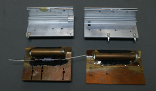
Based on this experience, I modified my main PC in several ways. First, I took the "fanless" Luxurae PSU
(the one with fan) and replaced the heatsinks by watercooled heatsinks. The images below show the old
aluminum heatsinks and their copper drop-in replacements with the copper tubing already sweat-soldered
to the plates. Also visible is the large 10W resistor that allows me to feed more waste heat into the water.
The right photo shows the heatsinks mounted on the PSU board, equipped with barbs and ready for
assembly. Note the ground wire in the foreground, which connects the heatsinks to gound. Als note the
thermistor in the background, which servers as an overtemperature shut-off.
|
Figure 11: Converting the "fanless" PSU with fan into a true fanless PSU with
watercooled heatsinks. Left: The original aluminum heatsinks juxtaposed with the
new custom copper heatsinks. The copper tubes have already been sweat-soldered to
the plates, but the barbs are not yet mounted. The power resistor from the snubber
network is visible, glued to the MOSFET plate. Right: Completed PSU with the heatsinks
in place. Both heatsinks are grounded. The NTC (green component in the rear) needs
to be placed strategically, because it controls the emergency overtemperature shutdown.
|
|

|
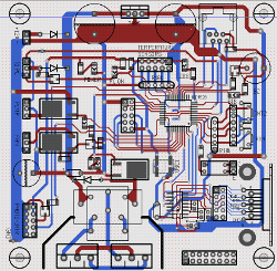
Next, I designed a rugged printed-circuit board for the monitor electronics. Unlike the first two versions,
where the monitor circuitry was housed in a separate case, the new version is mounted inside an old CD-ROM drive
shell and therefore fits a 5 1/4" drive bay. Four temperature monitor points exist: the PSU, the water, inside the
case right above the RAM and right at the monitor PCB. Uncomfortable temperatures (40 to 60 degrees C) inside the
PSU start a backup fan. Above 60 C, the computer would receive an UPS shutdown signal. This,
however, has never happened.
I then included another sensor -- a flow sensor (Adafruit item #828). Software was amended to display flow
rate with pump RPM and cause a shutdown event if the flow rate drops to zero. The monitor can now
shut down the computer in three alarm states:
- Overtemperature (Temperature point 1 exceeds 65 dgreees C)
- Pump failure (pump RPM drops to zero -- DC pump only)
- Flow failure (flow rate drops to zero)
- A low-water switch can be added easily as there is one more input pin available (not yet implemented)
The client is nutd, Linux' UPS tools.
|
Figure 12: Monitor electronics. The monitor operates independently from the
main PC system. A microcontroller monitors temperature and pump speed, and provides
a signal that "tricks" the motherboard into believing that the CPU fan is running.
The monitor is also connected to the serial input of the motherboard where is can
provide an upsd shutdown signal. Front panel elements include a LCD that
shows temperature and status information, and LEDs for power, pump, and alarm.
Left: PCB layout, right: Final PCB mounted inside a CR-ROM drive shell.
|
|
|
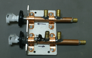
Another improvement came from replacing the various T- and Y- connectors that I used in the original designs. For
the new sytem, I created a manifold with three barbs sweat-soldered onto a copper tube (left image below).
The inlet tube has a NTC attached for temperature monitoring. The right image shows the manifold
built into the case.
|
Figure 13: Water connector manifold. The manifold replaces most of the T- and Y-
connectors used in the previous design. Barbs are sweat-soldered to a copper tube, and the
inlet and outlet tubes are mounted to an aluminum plate (left). The aluminum plate is then
attached to the PC case such that the quick-connect barbs protrude from the back of the
case (right). The three barb pairs supply the power supply, the cpu and -- with one Y-
connector -- the chipset and VGA branches. The lower tube features a temperature sensor
to monitor coolant temperature.
|
|
|
Ah, yes, the case! By coincidence, I was made aware of the Antec Lanboy. This is a computer case
designed for extreme airflow. Its top and sides are entirely made of a mesh that allows air
circulation. It comes with an insane number of fans, which I all removed (fanless, right?).
The image to the right shows a front view. The drive bays are used, top to bottom, for the DVD
drive, a memory adapter, and my monitor circuit. The Antec case has ample
space and air can flow quite freely in this configuration. Time will tell whether free convection
is sufficient in summer.
|
Figure 14: Front view of the final design. The third drive bay holds the
monitor electronics. The PC case has enough space to accommodate six hard disks
cooled by two large front-panel fans. The fans were removed to improve free air
flow. A 2.5" solid-state drive hides in a corner below the huge HDD bay space.
|
|
December 2016: Five Years Later
Hard to believe that I have now used this watercooled system for five years. It only failed once,
when the pump was seized up after a prolonged downtime over a vacation. Naturally, the monitor
indicated the problem immediately, and disassembly and cleaning of the pump fixed the
problem. I compare this to various fan failures I encountered on other systems and conclude
that the overall reliablility is dramatically higher than that of conventional
forced-air systems. Go figure.
The computer itself has been upgraded various times. I am meanwhile running an AMD
FX-9590 eight-core, a real beast of a CPU. If multiple cores are active, the
coolant can get really hot to the point that the auxiliary fan kicks in.
I also retired my trusty GeForce GT-640. It was a great card for this purpose, because
it never really ran hot, even under load. Its low contribution to the overall power
dissipation was simply amazing. However, modern CAD applications required a bit more
GPU power, and I replaced it by a GTX-1060 (got it below $200). As usual, this card
required massive modifications to allow GPU and MOSFET thermal power to be directed
into the water circuit. Risky -- this is why I limit the amount I spend on such
components, but the operation was successful.
The Luxurae PSU (the fanless one with fan attached) was also retired. It had
(or developed?) some coil whine that got on my nerves -- somthing that would normally be
drowned out by the fan noise so that nobody would notice. I decided to go straight
to the top and bought a Seasonic. I already had a really good experience with the
80-plus platinum fanless 480W PSU by Seasonic: solidly built, robust, and (not to be
taken for granted) it actually delivered according to its specs. My solution was a Seasonic
620W PSU, subjected to surgery the usual way: Replacement of the heatsinks by watercooled
units (home made), and removal of the fan.
It might be worth mentioning that none of my modified PSUs ever failed.
I retired some in working condition, such as my rebuilt 380W PSU (Part 1, Figure 9) and
the Luxurae PSU. I have one spare Seasonic. Two more are in use without any sign of trouble.
New pumps were developed as well. I found the Alphacool VPP655 to be much easier to
silence than my previous Thermaltake P-500. Notably, the PWM feature allows to select
a pump speed that minimizes resonance with the surrounding cabinet parts. For this reason,
I switched to the VPP655 pump and added a speed adjustment feature to the software.
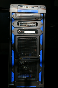
 The sandbox system, the second one I built shortly after the first one (which is my main
desktop), is also in full operation. I used a roomy Corsair high-airflow case, because
the Antec Lanboy was unfortunately discontinued. To make it truly high-airflow,
I replaced the side window by a mosquito mesh. I also wanted to experiment with dual
GPUs, so I added an auxiliary 12V power supply. The image to the right shows the
complete case. Some hint of tubing is visible underneath the mesh.
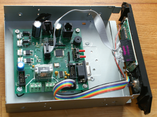
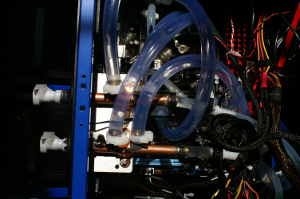
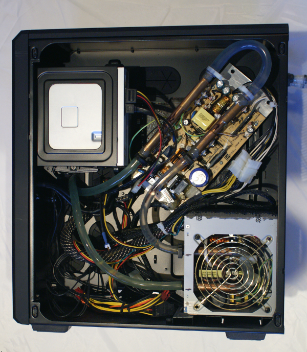
Below is a view of the inside. The CPU compartment reveals much cleaner tube routing
than I used to have (e.g., Figure 11). The right-hand picture shows the PSU compartment,
and the auxiliary PSU is clearly visible. The idea of using a second PSU is to
distribute the thermal load, and in this respect the design is successful.
However, for my (non-gaming) purposes, the dual GPU failed to deliver significantly
higher rendering power than a single GPU, and I eventually removed one card.
The sandbox system, the second one I built shortly after the first one (which is my main
desktop), is also in full operation. I used a roomy Corsair high-airflow case, because
the Antec Lanboy was unfortunately discontinued. To make it truly high-airflow,
I replaced the side window by a mosquito mesh. I also wanted to experiment with dual
GPUs, so I added an auxiliary 12V power supply. The image to the right shows the
complete case. Some hint of tubing is visible underneath the mesh.
Below is a view of the inside. The CPU compartment reveals much cleaner tube routing
than I used to have (e.g., Figure 11). The right-hand picture shows the PSU compartment,
and the auxiliary PSU is clearly visible. The idea of using a second PSU is to
distribute the thermal load, and in this respect the design is successful.
However, for my (non-gaming) purposes, the dual GPU failed to deliver significantly
higher rendering power than a single GPU, and I eventually removed one card.

|
|
Some time later, the watercooled family of PCs was joined by a third one, which served
as my music workstation. Clearly, a silent PC is of utmost importance for this application.
Since I settled on more or less the same design, there is nothing special about this third
PC, except that it is another PC system that works flawlessly and reliably.
Download links:
The hardware has advanced over the first iterations, allowing more sensors and a LCD
status monitor. The most recent circuit diagrams can be downloaded here, and these circuit
diagrams coerrespond to the PCB in Figure 12.
The software is written in PIC assembly. This link provides you with the most recent
control software. Most recent additions are the flow meter and low-flow alarm,
and the upsd shutdown facility. The software also contains numerous configuration switches
to reflect your display, pump, and sensors.
Download the assembly file here:
adv_control.asm. Optionally, add the LCD module to
your project. Use at your own risk - there is no warranty.
Software licensed under the
GNU Public License. Have fun.
To program the chip, use a PIC IDE such as the extremely well-written and flexible
Piklab. Create a new project and make both assembly files part
of the project source code, and it should create the hex code right away.


