Continued from part 2.
| Color | Label | Function |
| Red | R or Rh | 24VAC power from HVAC unit |
| Red | Rc | 24VAC power for cooling circuit (usually connected to Rh) |
| Green | G | Main blower relay |
| White | W | Furnace relay (in heat pumps, relay for heating) |
| Yellow | Y | A/C relay |
| Blue | C | Common (24V return) |
To turn on your furnace/heater, simply connect Rh to W. The HVAC unit starts the furnace sequence. Similarly, by connecting R or Rc to Y, the HVAC unit turns on the A/C compressor. Both functions implicitly start the main blower for air circulation. However, connecting R to G turns on the blower even when the HVAC unit neither heats nor cools. Heat pumps may need additional signals for the change-over valves (wires O and B). The blue wire (C, common) is the ground reference for the 24VAC power supply. R and C can be used to derive power for a thermostat.
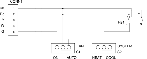
The thermostat could now simply be equipped with two relays. When the first one is closed (connecting R to W), the system would heat. When the second one closes and connects R to Y, the system would cool. However, a single relay is sufficient, because most thermostats have a slider for the mode of operation: Off, cool or heat. The advantage of the slider is that it is impossible to close R-Y and R-W simultaneously. A simplified circuit diagram that explains this principle is shown in Figure 4.
|
|
| Figure 4: Circuit diagram of a basic HVAC control. With slider S2, the mode (heat or cool) is selected. Relay Re1 is controlled by the thermostat. When it closes, the HVAC turns on. Slider S1 allows to turn on the main blower individually. CONN1 is a screw-terminal to attach the wires from the HVAC system. |
Thermostats are low-power devices, and the relay is often a latching relay. A latching relay stays in its present position unless a short current pulse to one of its coils moves it to one or the other position. Thus, a latching relay has two coils: A pulse on one coil places the relay in the "on" position, and a pulse on the other coil places it in the "off" position. Therefore, a latching relay can stay in either position for an extended time without drawing power (and thus draining, for example, a battery).
This gets us to the practical realization. When we moved into our home, the painters messed up one thermostat with paint. I used this thermostat for my prototype. This thermostat was a White-Rodgers 80-series non-programmable "dumb" thermostat and conveniently consisted of two circuit boards that I'll denominate "base board" and "control board", respectively. The base board contains the latching relay, the sliders (see Figure 4), some power conditioning and transient suppression, and -- most importantly -- a connector for the control board. The control board performs the actual thermostat function.
The schematic of the baseboard can be seen in this file:
| Schematic 1: | baseboard1.pdf | Base board schematic (PDF format) |
The elements of Figure 4 can be recognized. However, the base board performs additional functions. First, it informs the control board of the position of the system slider (heat, off, or cool). The same slider also provides the HVAC with control for the changeover valves (O and B wires). In addition, it can provide ~4V power from the 24VAC from the HVAC unit, albeit at low currents, up to 10mA. Battery backup is present. The rectified 24VAC signal is also routed to the controller, presumably to provide a "powergood" signal. Two transistors, Q2 and Q3, control the latching relay and can be directly driven from a microcontroller.
The contoller's function becomes more obvious now. A microcontroller interrogates the HEAT and COOL signals (CONN1 in the baseboard schematic). If either heat or cool is selected, the microcontroller measures the temperature, computes the control deviation and the on-time as described in the previous part. At the start of a cycle, Q3 receives a brief pulse to turn the HVAC on, and after $T_{on}$ elapsed, a short pulse for Q2 turns the HVAC back off.
Additionally, Q2 receives a pulse when the system slider is moved in the "off" position or when the main HVAC power fails. Presumably, this is the main reason for the battery backup: to maintain the ability of the controller to reset the baseboard to a defined (i.e., inactive) state.
| Schematic 2: | pwrsub.pdf | Power subunit schematic (PDF format) |
An additional feature of the power subunit is the voltage divider that illuminates the green LED and feeds the "powergood" signal. The 2k resistor and the LED drop the voltage to ~4V. This voltage is further smoothed and buffered in a 10μF capacitor and applied directly to the powergood input if the microcontroller. Lastly, there is the P-channel MOSFET IRFD9123, which controls power to the sensors. The sensors can therefore be powered down unless they are actively measuring.
| Schematic 3: | cpuboard1.pdf | CPU board -- microcontroller section |
| Schematic 4: | cpuboard2.pdf | CPU board -- miscellania |
Schematic 4 finally reveals some of the interconnects, a day-night LCD illumination, and some of the power buffering capacitors.
One desirable feature of the DS18s20 is the resolution of 0.1C, which allows an enormous improvement of precision over commercial devices that normally allow only 0.5C.
I have provided connectivity for up to four sensors. It is my plan to place several sensors along the hallway and measure an average temperature. At present, however, the software only supports two sensors. At least one sensor can be placed in the compartment to the far left in Figure 6 (the space with the vent slits). Placing a sensor inside the main compartment is not a good idea as the natural heat dissipation of the circuit makes its temperature reading too high by several degrees. Other sensors would be routed with thin wire. Aesthetics is definitely an issue here.
| Figure 5: Picture of the original thermostat, partially disassembled. The front cover, display, and keys have been removed to expose the control board and the base board underneath. Damage caused by the spray paint is evident. Click to enlarge. |

|
Figure 6 shows the base board inside the lower part of the thermostat case. Above the base board is the battery compartment (with two black wires). Highlighted are the screw terminals for the HVAC wiring (A), the 8-pin connector to the controller (B), the latching relay (C) and the sliders (D). The base board's circuit diagram is shown in Schematic 1. Also visible is some unused space to the left of the base board. This space will be used for the power conditioning subunit.
| Figure 6: Close-up of the base board. (A): Screw terminals to connect the HVAC. Letters corresponding to the wire colors (Rh, Rc, Y, W, G, ...) are visible. Also visible is a short between Rh and Rc. (B): The 8- pin connector that connects the base board with the control board. In the original, the 8 posts are soldered and can only be separated by desoldering. (C): Latching relay. (D): Sliders for fan (left) and heat/off/cool (right). Click to enlarge. |

|
I designed a PCB that has the same physical dimensions as the original White-Rodgers control board. The layout is shown in Figure 7. A side-by-side comparison of the new PCB and the original control board is shown in Figure 8. Note that the new PCB is upside-down and the cutouts therefore mirrored vertically. With the exception of the pushbuttons, the components are facing the base board. Apart from the two buttons for up and down (setpoint adjustment), four more pushbuttons exist: a reset button (emergency stop), a mode button to toggle between day and night modes, and the Menu and Enter keys for parameter adjustment.

|
| Figure 7: Layout screenshot of the controller board. The elements are very similar to those of the original White-Rodgers control board: Microcontroller, display, connector to baseboard, pushbuttons. On top of these, I added more pushbuttons and connectors to the power board. A programming connector is also provided to allow in-circuit reprogramming of the software. Click to enlarge. |

|
| Figure 8: Side-by-side comparison of the original controller board (A) and the new controller board (C). In-between is the power conditioning board (B) that fits in the space left of the base board. Some cutouts have not yet been completed. Click to enlarge. |
Figure 9 shows how the components fit together. Clearly, with a bit better planning, a suitable post connection could have been established between power subunit and control board, much like the posts connecting controller and baseboard. Right now, flexible cables establish the connection. Figure 10 shows the nexyt step of the assembly with the controller board put in place. Due to the poor planning of the connectors, the space between controller and power baord becomes very tight and crowded with wires (not visible in Figure 10). Instead of the battery, I decided to use a 1F super-capacitor that gets charged from the 5V regulator. It keeps the microcontroller powered for several minutes after a power failure, which is more than sufficient to recognize the power failure and move the latching relay into the "off" position.

|
| Figure 9: Partially assembled thermostat. The left picture shows the finalized board (Figure 8, right) with the key components: Microcontroller (partly underneath the clock crystal), real-time 32kHz crystal, a few scattered resistors and capacitors, connectors for sensors and the power board (right side) and the base board (left side). The pushbuttons are on the back side. The right picture shows the power subunit placed next to the base board. Click to enlarge. |

|
| Figure 10: Partially assembled thermostat (continued). Here, the controller board has taken the place of the original controller board, and connections to the power subunit and the baseboard have been established. The pushbuttons are now visible. These include the easily accessible "up" and "down" buttons (A) and the extended buttons (B). In place of a battery, I chose a 1F super-capacitor (C) that buffers power for several minutes. Lastly, the LCD (D) is attached and mounted inside the cover. Click to enlarge. |
Despite the venting holes, the leftmost compartment (see Figure 9) is unsuitable to house any of the sensors. There appears to be a heat source that makes the interior of the compartment appear approximately 2C warmer than the environment. It is possible that the regulator is responsible for the waste heat, although total power consumption is approximately 10mA on the 24V side, which means that the entire circuit consumes about 1/4 W. However, as shown in Figure 11, the sensors need to be mounted outside of the box. Although I had intended to run sensors to different places in the hallway, I hoped that at least one sensor could be hidden inside. This is not the case.

|
| Figure 11: Thermostat mounted on the wall and in operation. This prototype uses a 4-line display that shows (from top to bottom) the operation mode and the setpoint temperature, the sensor temperatures, the status of the current cycle, and the control deviation and time offset. The additional function buttons are integrated into the case somewhat unelegantly, but a cover (shown open) normally covers those buttons. Click to enlarge. |