At first, I ran the radiator and the Grainger hydronic element in parallel -- out of convenience, because I didn't want to disassemble the entire system. Eventually, after I had to disassemble the complete water cooling assembly, I removed the radiator. The hydronic element dropped the temperature by about 10 degrees C; removing the radiator dropped the temperature by another 2 degrees. This is counterintuitive at first. However, the radiator probably did not contribute much to the cooling part once the temperature difference to room temperature dropped below 10 degrees. Improved flow would improve cooling efficiency. The idea here is to keep the flow circuit simple.
The sound emitted by the present pump assembly is barely audible. This is now satisfactory for me. I guess most people would not hear anything, and the slightest whisper of wind outside drowns out the pump noise. It is far below the measurement limit of my sound meter.
To use my repaired PSU, I replaced the odd 5W resistor (dissipating 7W, remember?) with a 10W type and mounted that resistor on the heat sink to get its heat into the water rather than the air inside the PC case. I also provided a heat sink for the secondary inductors with the same purpose. A NTC allows me to monitor the temperature inside the PSU, which usually equilibrates near 38 - 40 C. This temperature is fully acceptable, particularly since the power semiconductors are not warmer than that, being mounted on well-cooled heatsinks.
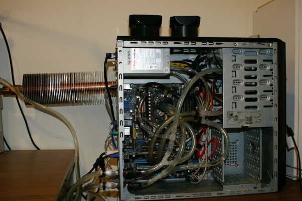
| Figure 10: Picture showing the complete system. Visible behind the PC is part of the 1m (3 ft) hydronic element. Also notice the two "chimneys" on top of the case. These are to prevent me from using the top of the PC as a horizontal surface to deposit things, which would cover the exhaust holes. The holes in the top of the PC ase are important to allow warm air from inside the case to rise and thus create some kind of natural convection-induced air flow that expels warm air from inside the PC case, To the right is the carpet-padded cabinet with the pump and reservoir. |
|
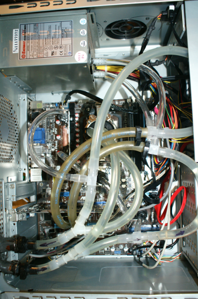
Figure 11 shows a close-up of the PC interior. In spite of the apparent mess of tubing, routing of the tubes is straightforward, much like a ladder with four rungs. The first rung (3/8" tubing) provides water to the CPU. The second rung (1/4" tubing) leads to the southbridge, northbridge, and MOSFET blocks in series. The third rung goes into the VGA waterblock (3/8"), and the last rung (1/4") lets water flow through the power supply. Some excess length tubing could be trimmed, and I may do so eventually.
| Figure 11: Detail of the PC interior. The tubing appears to be more tangled than it actually is. Water enters the case at the lower quick-connect barb. The tubing then splits into a CPU branch and a branch for the other waterblocks. From the second branch, the 1/4" tubing splits off that leads to the chipset. Further up, the branch splits again into the VGA branch and the power suppy branch. |
 |
At a room temperature of 24 C (on a nice, sunny February day in Georgia), the water runs at 28 C, and CPU load has barely any influence on the water temperature. The VGA chipset measures 39 C, the motherboard sensor 34 C, and the CPU 36 C (no load). With all four cores under load, the CPU temperature rises to 50 C, driving the water up to 30 C. The power supply shows air temperatures of 40 C (no load) to 45 C (full load). The fluid (2 liters of distilled water with two drops of Triton-X) remains clear, and no growth has occurred (yet). The 2 bars of 4 GB memory (OCZ Reaper series) deserve special mention, because they generate almost no heat. I considered RAM cooling, but with this memory, there is no need.
One of the things I learned is that watercooling equipment is often overpriced and also incorrectly advertised. The two most blatant examples were the Thermaltake P500 pump and the "fan-less" power supply. The pump was supposed to run with 16 dB sound emission (see decibel table here), but its actual sound was more in the vicinity of 40dB environments. The PSU was supposed to be fanless with 0dB, yet it came with a fan that emitted between 30 and 50 dB, depending on temperature. I also tested high-end thermal compound against a cheap silicone compound that I bought by the bucket and found no temperature difference in the CPU. Considering the high price per gram of some thermal compounds, I conclude that many of these are a rip-off.
As a further improvement, I tried to build a Peltier chiller. The idea is to run water through a waterblock in contact with the cold side of a Peltier element and dissipate the heat through a heatsink from the hot plate. My initial design did not work well. The Peltier element draws almost 6A at 12V and therefore creates 70W heat on its own that need to be dissipated. I mounted a massive CPU heatsink, but without forced convection temperature rises easily to 60-70C, while reducing water temperature by only one degree. The additional 6A load also increases heat dissipation in the PSU. I conclude that the heat generated by a Peltier element is too high to be expelled from the system, which defeats its purpose. For extremists, a two-circuit system could be imagined where one hydronic element cools the PC water circuit. After initial cooling, the water is led through a Peltier chiller with several Peltier elements. A second water circuit (needs pump, reservoir, and hydronic element) dissipates the heat from the Peltier elements. I believe that this combination would drop the primary (PC) water circuit by another 5 degrees or more, but the secondary circuit can well double as floorboard heater. Is it worth it? I don't know.
Is the entire system worth the effort? For noise-sensitive people, the answer is clearly yes. The reduced noise level is amazing. I am happy I did it.
After one year: The third part describes my experience after one year of operation.